Bruin Formula Racing (BFR)
Technical Director: June 2022 - May 2023
Suspension Design Lead: June 2021 - June 2022
Suspension Manufacturing Lead: April 2020 - June 2021
Suspension Subteam Member: September 2019 - April 2020
Bruin Formula Racing is an engineering student organization at UCLA that competes in the international Formula SAE competition. The goal of the competition is to design a formula style racecar to compete in static and dynamic events at various competitions throughout the year. Designing and manufacturing a racecar from scratch presents many difficult engineering challenges, giving students the opportunity to learn and gain real-world engineering experience.
During my fourth and final year on the team, I was the team’s Technical Director, working alongside 2 other Managing Directors and 1 Financial Director to lead a 100+ person team. Among other responsibilities, my main job was to oversee the design, manufacturing, and testing of our 2022-2023 vehicle, Mk. VIII. My focus was improving our vehicle’s raw performance and attention to detail, as well as advancing the robustness and “legitimacy” of the team through completely new standards (safety, engineering, IT, etc.), engineering processes, documentation, and project management methods. At the May 2023 FSAE IC competition at Michigan International Speedway, our team placed 10th overall out of 120 teams. This was our team’s best result ever and a culmination of everyone’s incredible dedication over that past year.
Due to COVID-19, our team took a two-year design cycle from 2020-2022 as opposed to the typical one-year design cycle. Thus, we spent all of 2020-2021 designing a completely new car for the 2022 FSAE competition. During the 2021-2022 academic year, most of the focus was on building out that design. At that time, I was the Suspension Design Lead, meaning that I was in charge of managing the entire suspension team to successfully design and manufacture the car’s suspension system. Previously, I was the Suspension Manufacturing Lead, meaning that I was responsible for assisting in the design of the suspension and ensuring all suspension parts are designed such that they can be manufactured within the team’s capabilities. As a CSSW subteam member my freshman year, I was responsible for completing new member projects (alignment jig detailed below) and manufacturing suspension and chassis components like plugs and welding fixtures.
Mk. VI Manufacturing Cycle: Toe Alignment Jig
When I was a new member, one of my first projects was designing an alignment jig for the car. Previously, to adjust toe and camber angles, we had to go through a tedious process of setting up jacks precisely around the car, tying strings to connect them all, and then measuring wheel distances from those strings. Not only did this take a long time, but it also wasn’t too accurate, and anytime anybody accidentally kicked a jack, the entire process had to start over.
I was tasked to design and manufacture a design to solve these problems, along with two other new members.
Our new design fixed both problems of quick setup and accuracy. By mounting directly to openings in the chassis, the mechanism can easily slide on and off, and also will be accurate relative to the car every time. A key consideration for this design was the cost, as our budget was quite low for this project. The original design used steel and welding, which was quite expensive, especially when factoring materials and hardware for the welding jig as well. After cost analysis, I realized we could save over $200 by switching to PVC an 3D printed components. PVC is can be bought cheap from Mcmaster-Carr and 3D printing is free at the UCLA Makerspace. Thus, I redesigned the entire jig to be made of PVC and custom gussets instead, drastically lower cost and manufacturing time. Unfortunately, due to COVID-19, the design was never fully manufactured, but it will be modified and finished for the next revision of the car.

PVC and 3D printed version of the front alignment jig

Final front design on the chassis

Alignment jig concepts on the front and rear of the chassis

Entirely PVC version of the rear alignment jig

Halfway finished alignment jigs. Manufacturing was cut short due to COVID-19
New Member Design Competition
During spring and summer quarter of 2020, the CSSW (chassis, suspension, steering and wheels) subteam hosted a virtual design competition since we didn’t have any shop access to work on the car. The aim of the competition was for teams of new members led by returning members to design a fully functioning car with only the CSSW subsystems. On my team, I led the design of the suspension system. I determined the suspension kinematics and geometry based our design goals, and modeled the essential components in Solidworks. At the end, we presented our design to senior team members for critiquing and evaluation. While the design isn’t perfect, it was a great first introduction to vehicle dynamics and suspension design, and gave me a solid foundation when designing the actual suspension.

Full CSSW subsystem CAD

Front suspension geometry sketched in Solidworks

Rear suspension geometry sketched in Solidworks

Front suspension CAD
Front suspension CAD

Full suspension subsystem CAD

Concept sketch/part used for geometry and kinematics calculations
Mk. VII Design Cycle: Front Suspension Packaging Iteration
For the 2020-2021 academic year, I lead the team designing the pullrod/shock system for the suspension. The focus was on finding the most efficient way to package the front suspension. This means:
Minimizing the forces on each suspension member, and thus minimizing their weight
Ensuring ease of manufacturing, assembly and adjustability after assembly
Strategically deciding the mounting points of the suspension on the chassis, thus reducing the forces on the chassis (and thus tube weight), as well as the number of tubes required to make every mounting point be a “node”.
The process for finding the ideal design was a combination of creative iteration and engineering validation. We first brainstormed as many ideas, crazy or not, as we could, and then modelled and ran calculations on the most feasible ones to objectively determine which is the best. Below were some of the ideas, each of which had statics calculations ran to determine forces in each tube, as well as weight comparisons. Much of this effort was in collaboration with the chassis team, as a huge part of the design was to determine how to best mount the suspension to the chassis. We had to work with their requirements as well, when it came to where tubes could be placed and the maximum forces the chassis could take.
Ultimately, after many design iterations, we chose to go with Design Idea 1 (as shown below), as it had the shortest pullrod, exerted no out-of-plane forces on the bellcranks, and also was just the simplest to manufacture and assemble. Our concern with the shock mounting point being in the middle of a tube was alleviated after running rigorous FEA on the chassis to ensure that the deflection in that tube contributed a negligible amount to the shock’s effective stiffness, and that the stress experienced by the tube was well within our Factor of Safety.

This design, “idea 2”, is a bit more creative, as it places all the components within the double-wishbones, or a-arms, themselves. Both the bellcrank and shock mount at existing suspension pickup points, meaning no extra chassis nodes or tubes are necessary. However, the large angle of the pullrod relative to vertical means that it experiences much larger forces compared to idea 1. Furthermore, this design is harder to manufacture and assemble due to multiple things mounting at the same points. It also might not be possible to hit our desired motion ratios with the design simply due to geometric constraints.

This design, “idea 1”, was the first one we came up with. It was heavily inspired by previous years’ designs, but keeps the pullrod and shock in one vertical plane, thus eliminating any bending moments on the bellcrank (the triangular piece). While this design is the simplest of the bunch, it places the shock mounting point in an awkward position, meaning the tube it mounts to could bend easily as it is not mounted at a chassis node.

This design, “idea 3”, goes a completely different route by placing the shock near the center of the car, away from the rest of the suspension. This makes mounting relatively simple, and also keeps the CG of the whole suspension very low. The main downsides are that the lower aft a-arm pickup point is now much further forwards, thus increasing the force it experiences, and the shock isn’t mounted at a node. The tube it’s mounted on is also a safety critical member (lower side impact member). Lastly, there were some interferences with this design and the sidepods.

The was the overall path taken when I designed the bellcranks.
Mk. VII Design Cycle: Bellcrank Design and Analysis
Given that we had a full year to design the car for the 2022 FSAE competition, we spent a rigorous amount of time poring over the details for each part on the car. More specifically, I focused on the design and analysis of the suspension bellcranks (also called rockers). Bellcranks are typically used in double wishbone pull/push rod suspension configurations. They direct the forces from the pull/push rod into the shock. Their specific geometry determines the suspension’s motion ratio, which is the wheel displacement / shock displacment. The motion ratio plays a large role in how the vehicle handles and the amount of force that actually gets transmitted to the shock. Thus, the geometry of the bellcrank must be very precise and intentional to achieve our desire motion ratios. The bellcrank must be lightweight while also stiff, as it is part of the unsprung mass. To design and validate the bellcranks, I took a three step process:
Motion studies in NX to determine motion ratios and optimize bellcrank geometry
Topology optimization in Altair Inspire to minimize weight while achieving FoS targets
General FEA and Non-linear buckling FEA in NX to ensure thin plates don’t fail under expected loads.
This video shows the suspension model in the NX motion study moving through its full range of motion. Sensors would measure the wheel and shock displacement during the travel to output the motion ratios onto graphs afterwards.
Step 1: Motion Studies
Rather than manually adjusting the motion of the suspension and measuring wheel displacement vs. shock displacement, I built a custom suspension model in NX Motion Studies to automate the process. This drastically reduced the time between iterations and allowed us to really take the time to nail down the precision and accuracy of our motion ratios. The model essentially allowed us to simulate motion in the shock, and thus the rest of the suspension components. Each component in the model was jointed to other components as they would be in real life. Then, sensors were added to the wheels and shock, and the readings from those sensors were outputted onto convenient graphs displaying the motion ratio vs. time, maximum range, and linear average (as seen in the table above). After each trial, the bellcrank geometry would be adjusted slightly to inch closer to our motion ratio goal until the average and range were at desirable values.
Step 2: Topology Optimization
Topology optimization is a mathematical method which determines the most efficient way to distribute material in a part within a defined space. It minimizes the amount of material used in a part while maintaining its mechanical strength. There are many topology optimization programs out there, but I used Altair Inspire, as some of our previous team members had used it in the past and had good experiences with it. Using Inspire, I was able to reduce the weight of both the front and rear bellcranks by 64%.
Step 3: FEA/Non-linear Buckling Analysis
Before and after performing topology optimization on the bellcranks, I ran them through NX FEA to ensure they stayed within our FoS. More specifically, I focused on buckling analysis, as these are rather thin plates experiencing forces exerted length-wise. Using NX SOL 106 Non-linear Buckling, I determined that the actual loads on the front and rear bellcranks were about half of the critical buckling loads for Mode 1 buckling, meaning that compression/tension (depending on pull/push rod) would be our failure mode, not buckling.
After performing these three steps on both the front and rear bellcranks, we arrived at the finalized designs which are robust, lightweight, and allow us to have accurate and precise motion ratios.

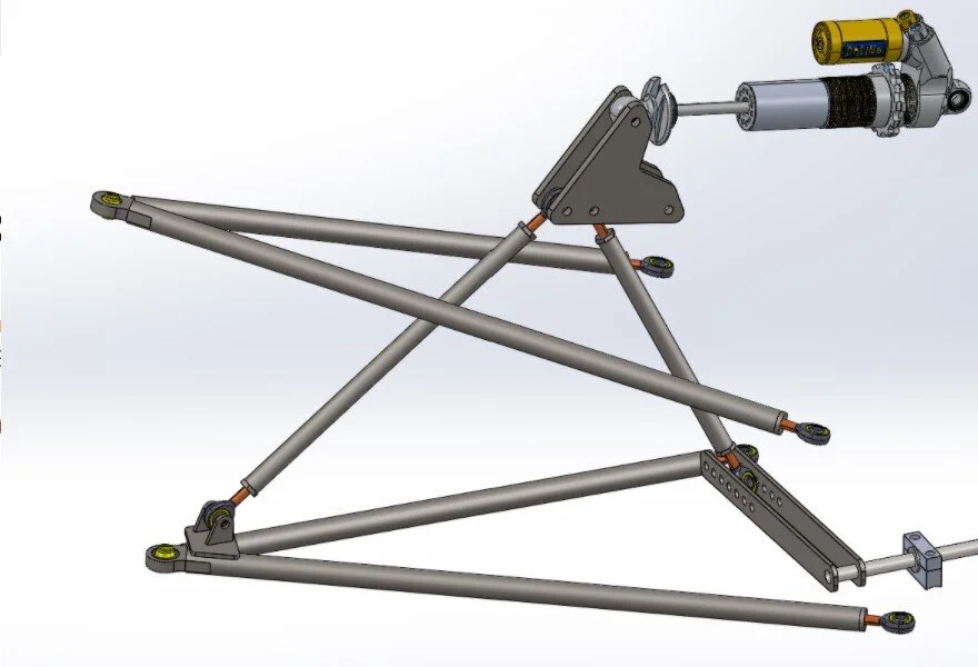
Finalized front bellcrank integrated with the rest of the front suspension.

Finalized rear bellcrank integrated with the rest of the rear suspension.
Mk. VII Suspension Manufacturing Cycle
For the 2021-2022 season, our team was fresh out the design cycle for our car, Mk. VII. Since we had all just gotten back to campus for the first time since the pandemic started, we were essentially seeing our shop for the first time again. Us leads were responsible for getting Mk. VII built without ever having actually built an FSAE car. This led to a slew of challenges but ultimately helped me learn on my feet and allowed to team to “reset”, at least in terms of establishing manufacturing practices from scratch, sponsor relations, etc. The manufacturing cycle started roughly in October and ended right before our competition in June 2022. While we had planned for around a month of testing, our inexperience led to our entire manufacturing cycle taking much longer than expected, pushing us right up to the deadline of competition. Despite being very crammed, we ended up placing 5th overall out of 48 IC teams at the June 2022 FSAE Michigan competition, which at the time, was the team’s highest placement ever. Below are some highlights from the manufacturing cycle for Mk. VII. They focus on the suspension system, as that was what I was responsible for as Suspension Design Lead that year.

Control arm welding fixtures. The plates are waterjet and accurately constrain the hard points of the suspension system.

Completed front suspension assembly. This picture was taken after the powder coating process and a few testing sessions.

Welding fixtures for control arm and shock-bellcrank tabs. We used a combination of waterjet and 3D printed components to fabricate these quickly. The fixtures are attached to a square-tubing frame system which accurately locates the chassis and gives us datums to reference from.

Test-fit assembly of the front suspension. Before powder coating the chassis, we test-fit as many systems onto the chassis as possible to check for any interferences, welding issues, assembly fitment problems, etc. If any issues are found, we then have the chance to address them without a layer of powder coat getting in the way.

The 2021-2022 team! We placed 5th overall out of 48 IC teams at the June 2022 FSAE Michigan competition.
Mk. VIII Technical Director
As Technical Director for the team’s 8th car, I implemented various new processes and initiatives to increase the “legitimacy” and robustness of the team. Below are some of the key things I implemented, all of which did not exist before.
Teamwide project management platform - Asana
Specific projects for the directors team and each subteam and subsystem
Big picture timelines, milestones, and updates viewable by all team members
Specific manufacturing trackers
Welding tracker for all insourced and outsourced welded components
Issue tracker for all non-nominal issues from minor issues to major risks. Used to manage mitigation status and priority in relation to Running Car status
Nominal parts tracker to manage overall assembly process of vehicle
Teamwide documentation/wiki platform - Notion
Team Home
Compilation of team history, constitution, directory, and links to all standards
Knowledge Base
Repository consisting of general knowledge applying to all car model years
Cars
Detailed pages for everything about specific car model years (goals, requirements, decisions, testing databases, change logs, manufacturing planning, design review slides, etc.)
Meeting Notes
Repository consisting of meeting notes from every meeting on the team, from director-level to subteam tagups. Viewable by all members on the team
Standards
Engineering Standards
Standard practices for SOLIDWORKS, GrabCAD, the design cycle, goals, requirements, decisions, analysis, hardware/fasteners, testing, and more
Engineering drawing approval process and custom BFR standardized templates
Design Freeze closeout document
Detailed list of every open design task on the entire vehicle, necessary to be completed before Design Freeze
Approvals and signoffs from every RE, Lead, and Director for each subsystem. All signatures are required before manufacturing can begin
Use of margins of safety and teamwide design factor requirements
IT Standards
Consolidation of all team communication to Slack
Standardized software for various tasks on the team
Shop Standards
Compilation of shop policies, hazardous waste disposal, shop issue report forms, and SOPs
Daily shop cleanup policies
System Integration
Vehicle->subteam->subsystem->component level responsibility breakdown
Cascading goals and requirements with documentation and naming conventions
Top-level vehicle goals and requirements, cascading down to subteam and then subsytsem level goals and requirements. All design decisions feed up to top-level goals and requirements
Decision matrices
Naming convention and documentation procedure, applying to all major decisions on the car
BFR Unified Hardware
Standardized hardware system for all fasteners on the car, with portable kits to bring to all testing sessions and competitions
Unified toolsets to allow several people to work on car at once
Testing
Test session setup, documentation, and data review procedures
Notion database with templates, packing lists, pre-run checklists, goals, setup tracking, and run indexes for every test session
Data management system
New data naming conventions and organization to compile every single ECU log, CAN log, GoPro onboard, and spreadsheet in Google Drive. Viewable by all team members
Comprehensive testing plan with #1 priority of maximizing drive and dyno time
6X dyno sessions (61 total dyno pulls)
8X shakedowns
4X Willow Springs testing days
1X endurance
44X acceleration tests
59X skidpad tests
Custom racing-simulator built from previous vehicle (Mk. IV) chassis
Used extensively for driving tryouts, benchmarking, training, and team social events
Safety
Vehicle pre-run checklists with all checks needed to safely start the engine/vehicle
Standard Operating Procedures (SOPs)
Written documentation and approval process for all safety-related operations and tasks on the team (turning on the car, starting the engine, jacking up the car, etc.)
Team members must read and complete SOP training before being able to perform the task for that SOP
Lunch n Learns (LnLs)
Training sessions for SOPs, hostable by anyone who has been authorized as an SOP trainer
Short, fun, sessions for anyone on the the team to host about any topic, usually relating to racing/cars
At the May 2023 FSAE Michigan IC competition, we placed 10th overall out of 120 teams, which was the team’s best competition result yet. Mk. VIII placed 6th in the Endurance event. Another highlight at competition was the Design Event. My presentation portion of the event (System Management/Integration) scored 17/20 points which was the highest score given to any team at the competition.

Mk. VIII in its early stages at the end of Buildathon. Buildathon is our annual 24 hr build marathon. It usually occurs immediately after we receive parts back from powder coating and is the start of our final assembly phase. If you look closely, the hubs and uprights in this picture are actually 3D printed, as one of our sponsors had a delay with their lead time. We quickly printed out some prototypes to have as placeholders for the actual 7075-T6 aluminum CNC machined parts which arrived a few days later.

Mk. VIII at its first testing day at Willow Springs, featuring the livery in its early stages. This was the first test of the entire aerodynamics package.

The 2022-2023 team!

Mk. VIII completing a dyno pull at our amazing dyno sponsor, Church Automotive Testing.

Mk. VIII whipping it through the Endurance track at competition. We placed 10th overall out of 120 teams and 6th in the Endurance event at the May 2023 FSAE Michigan IC competition.

Our trophy for placing 10th overall at competition.